Construction Scale Photogrammetry
Regarding small scale, architectural photogrammetry it would be advisable to initially define what is meant by ‘small-scale’.
By small-scale I’m primarily referring to 1:100 and below with the purpose being to determine the quality and structural status of specific building components.
Such scans can be done separately and incorporated in a larger project brief should the overall project scale be of a large construction or of an urban block, or they could be extracted from medium sized scans if those are planned and documented in higher levels of detail.
Below are a series of examples on the sort of analytical processes and diagrams that could be generated from such scans.
Example 1 : Ruined Staircase / Ag. Sozomenos
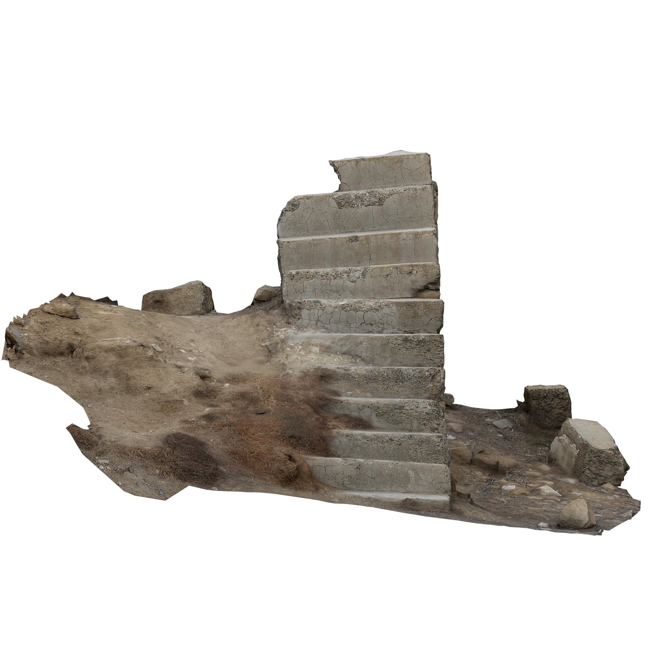
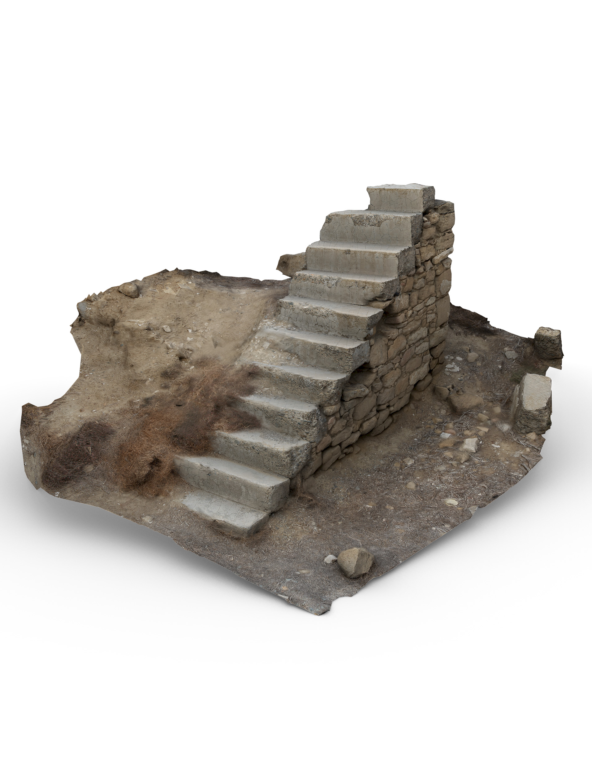
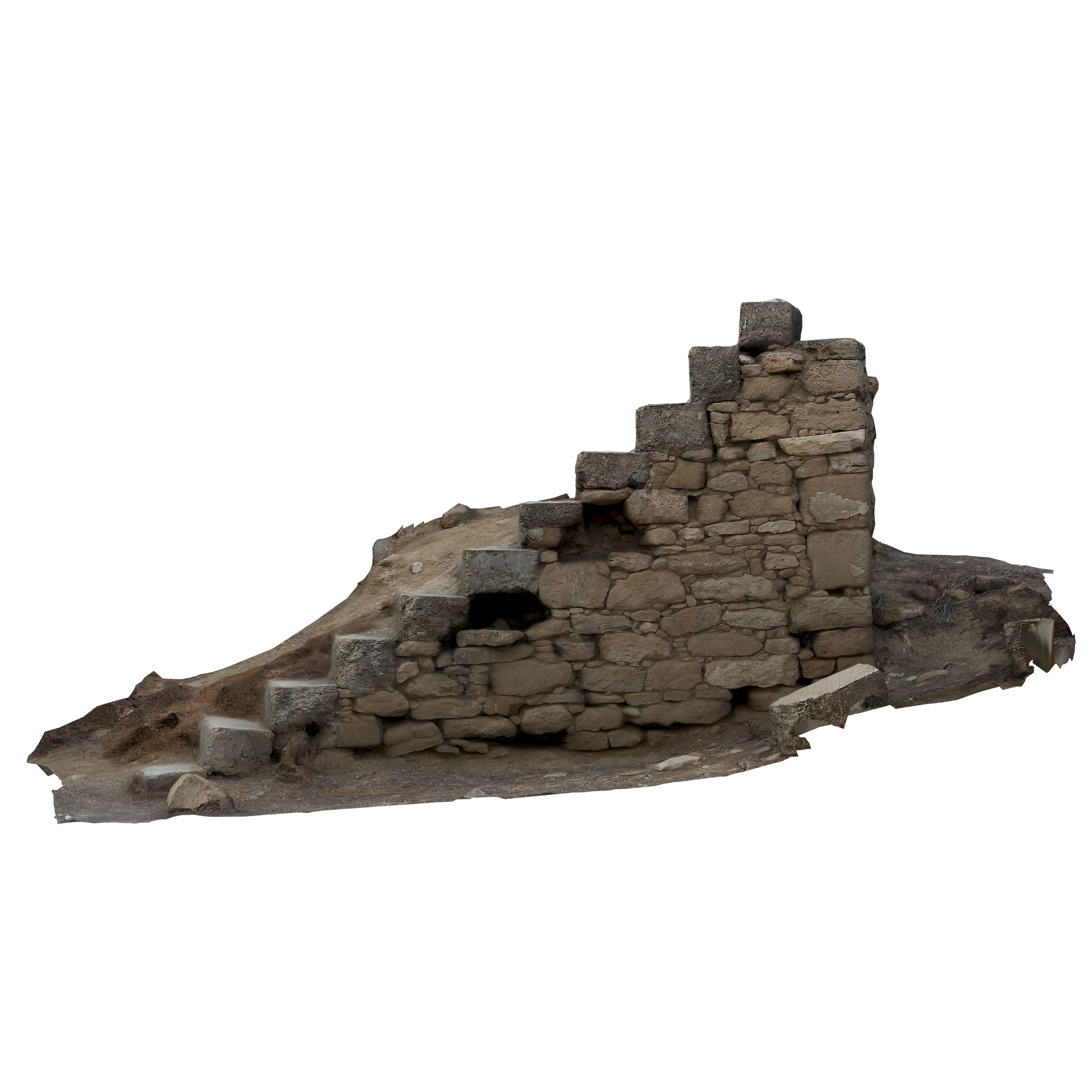
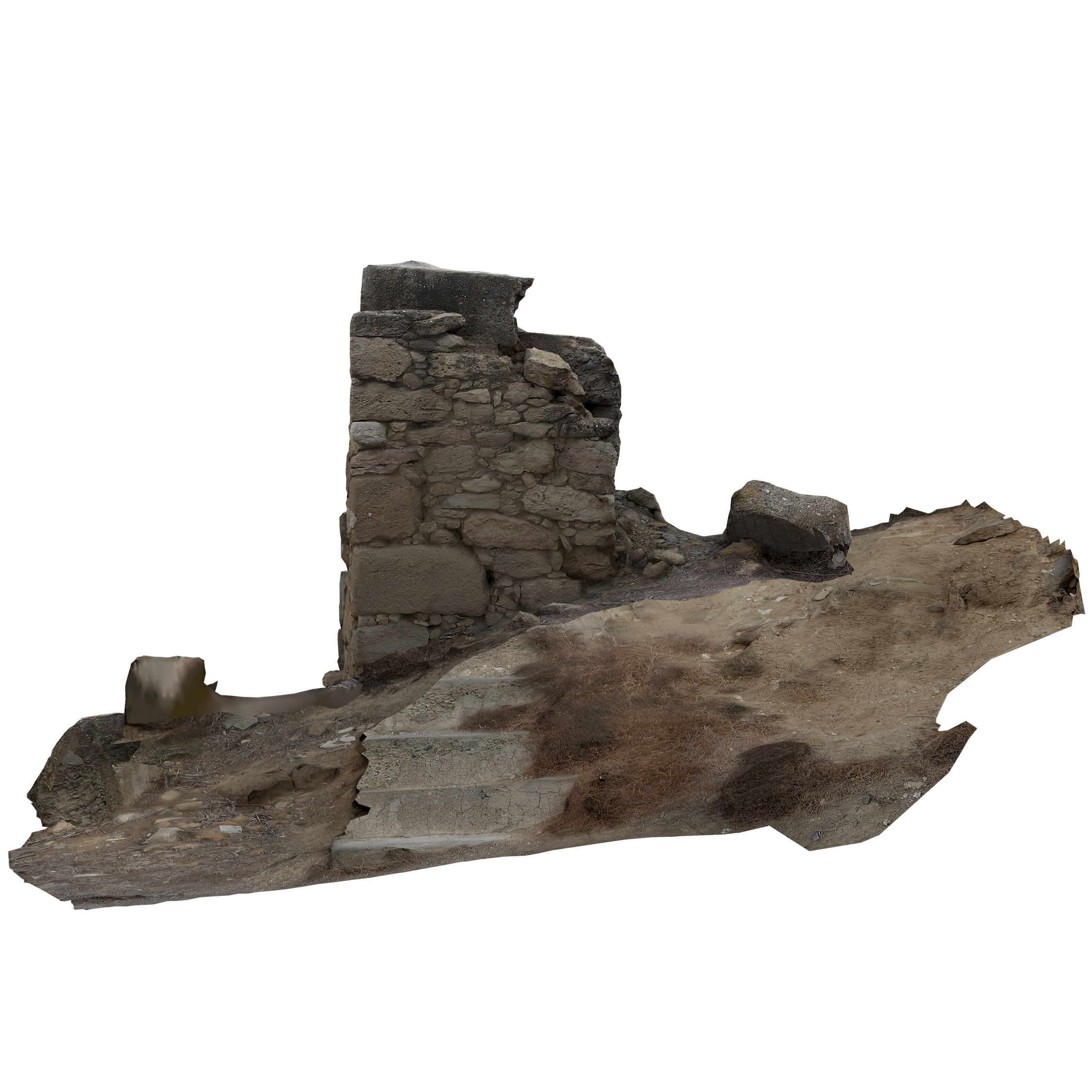
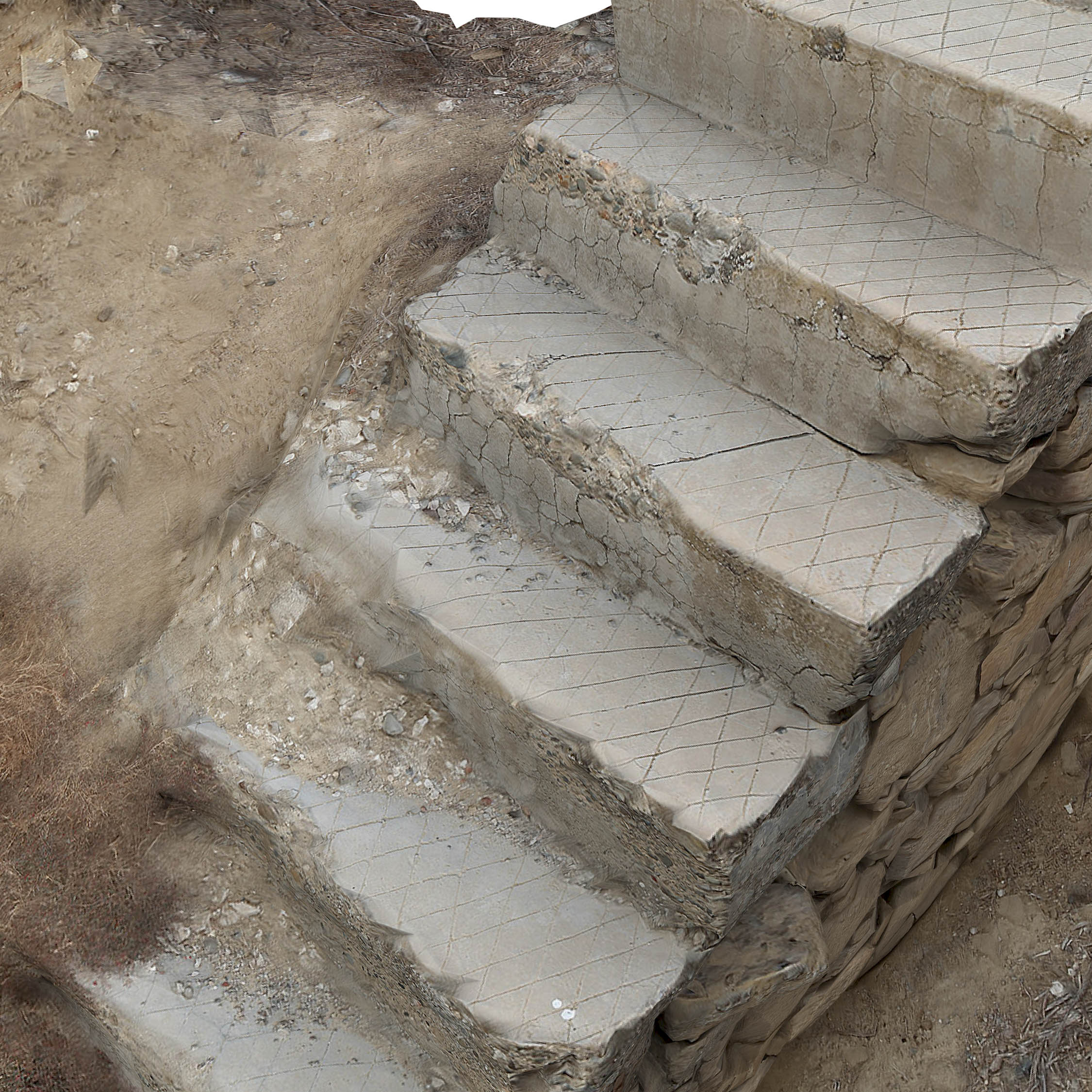
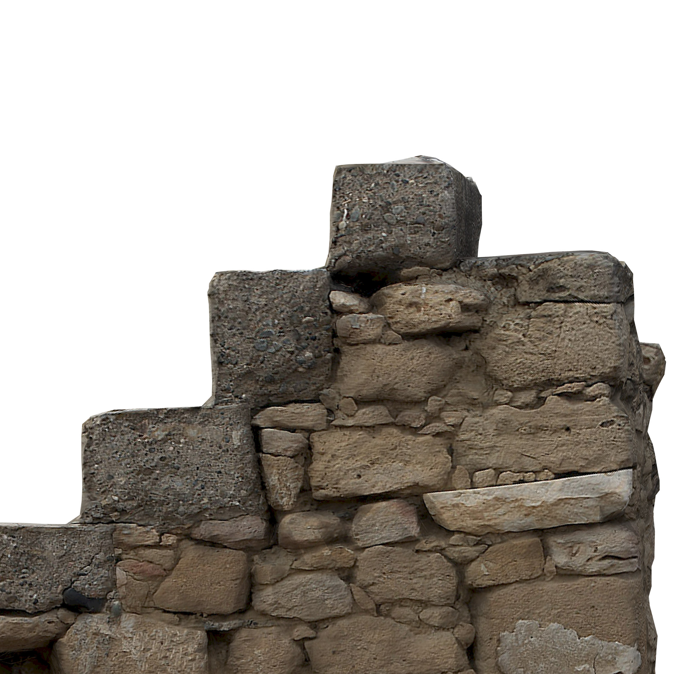
The first example is a scan of an old, ruined staircase in the area of Agios Sozomenos, a few kilometers outside Nicosia. The staircase was selected to be used as an example for close-range, terrestrial photogrammetry, with the pathology exhibited being evident enough to easily facilitate analyses in terms of its current structural integrity and forecast future degradation.
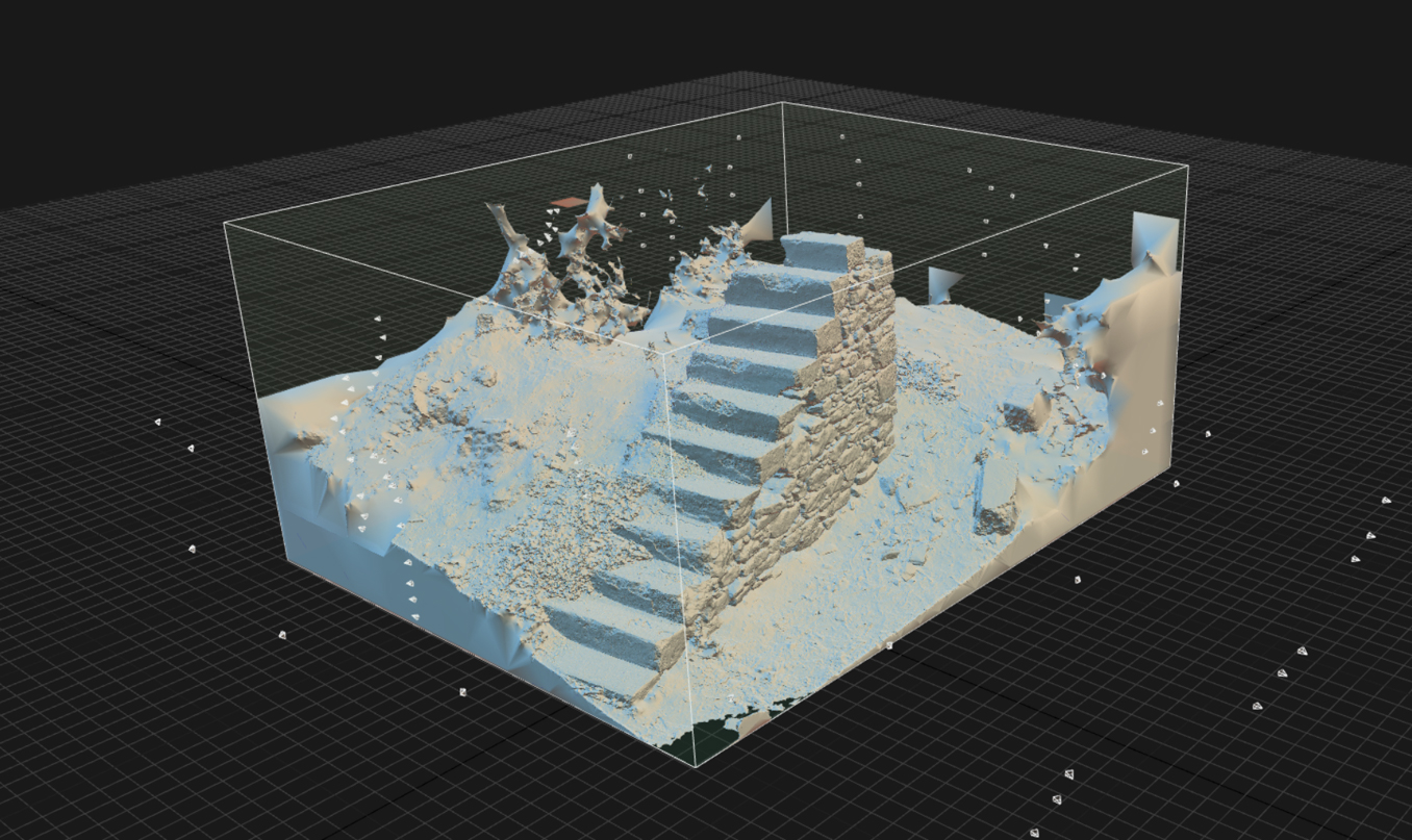
The below images show the final generated mesh, fully UV’d and textured with some of the surrounding terrain.
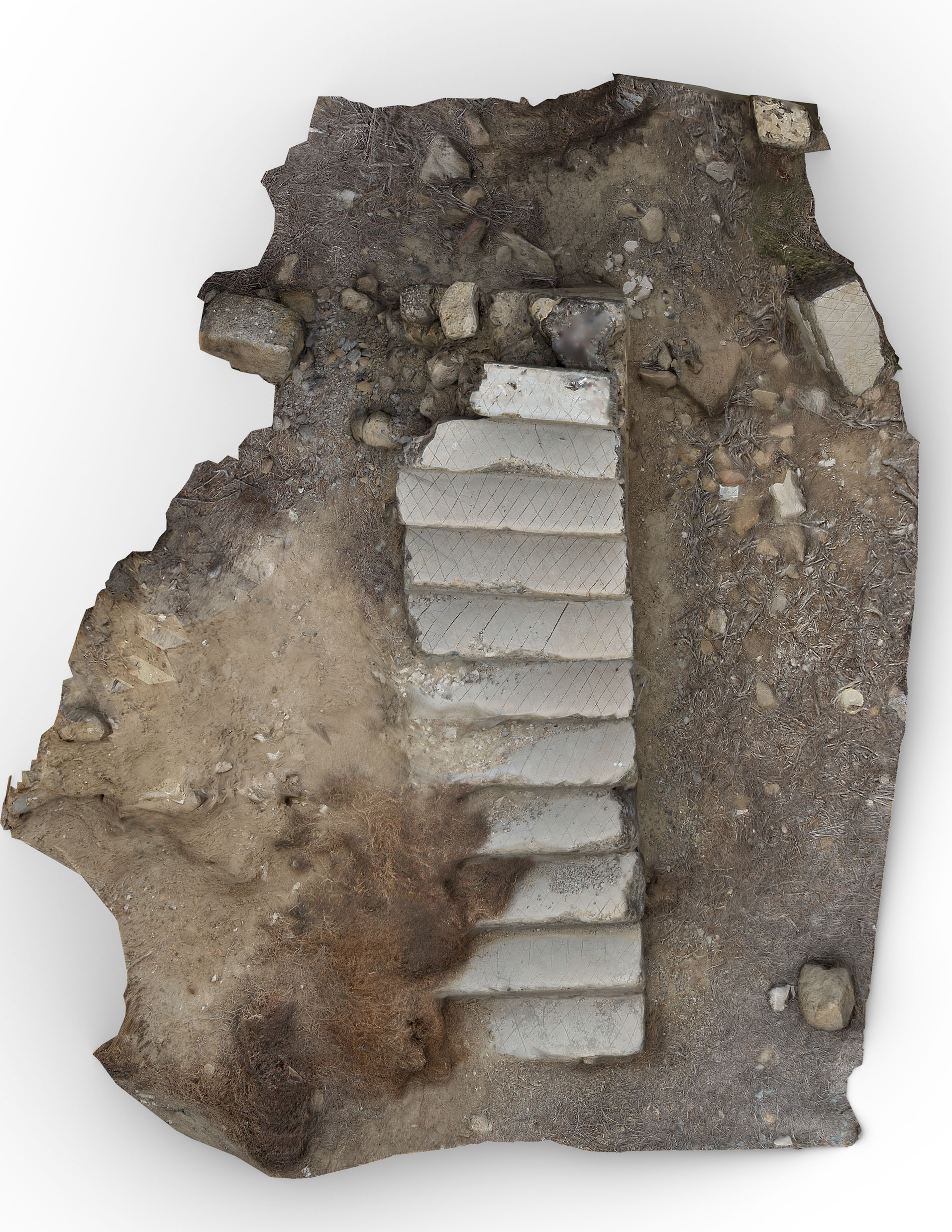
Scan Methodology
As briefly mentioned above, the particular scan was made using terrestrial photogrammetry exclusively, with around 120 images being taken in total.
The camera used was a Canon Mark II DSLR camera with a 24-70mm f/2.8 Canon L zoom lens, with the aperture being set to f/8, and the shutter being above 1/250. As this was during the daytime, the ISO was similarly set to 100.
The images were taken peripherally with the staircase situated in the middle of the shooting frame and were largely shot at around the 35-50mm range so as to avoid any distortion shooting completely wide could introduce. Three rotations at different elevations were carried out, along with some top down and close up supplementary shots.
The below diagrams illustrate the shooting methodology along with the initially generated point clouds and initial meshes.
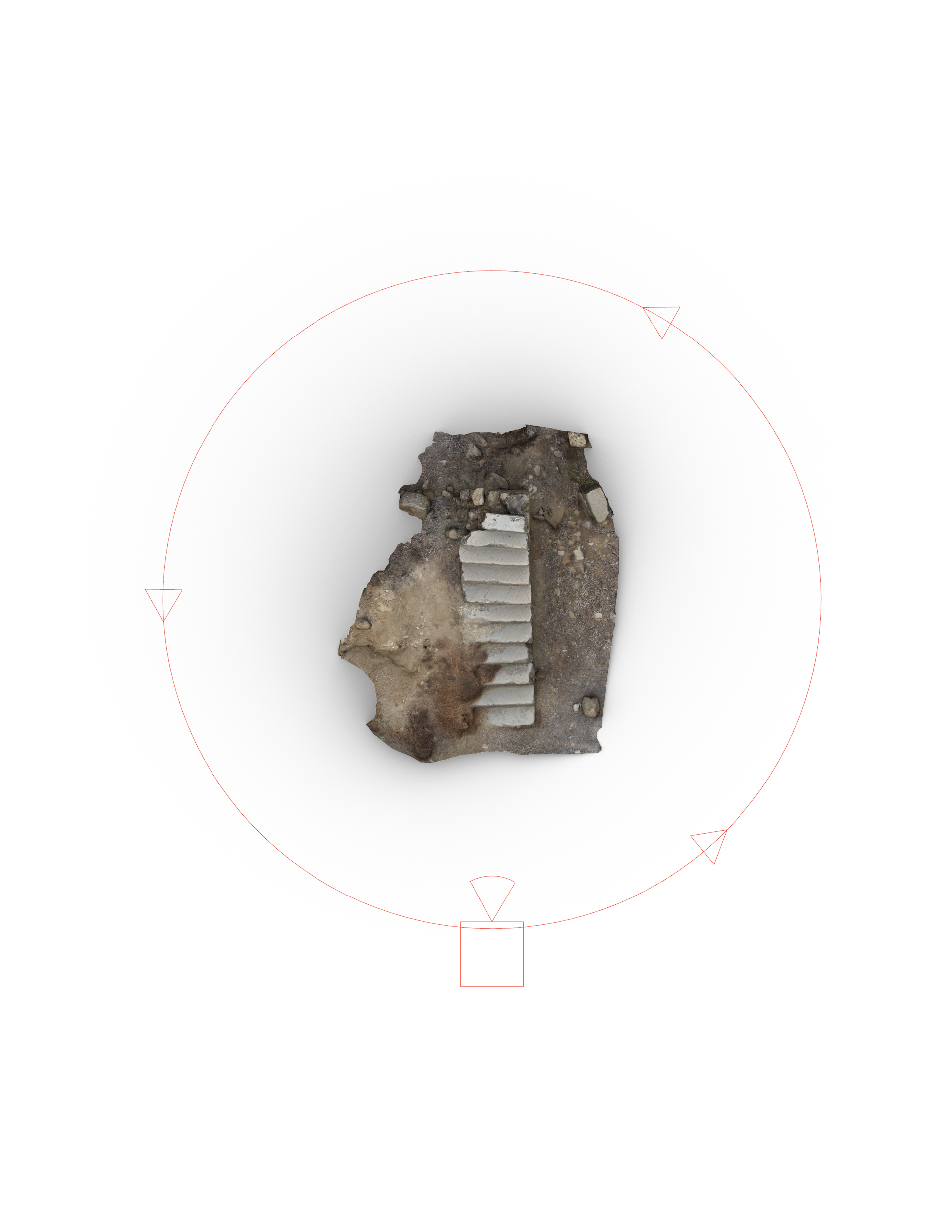
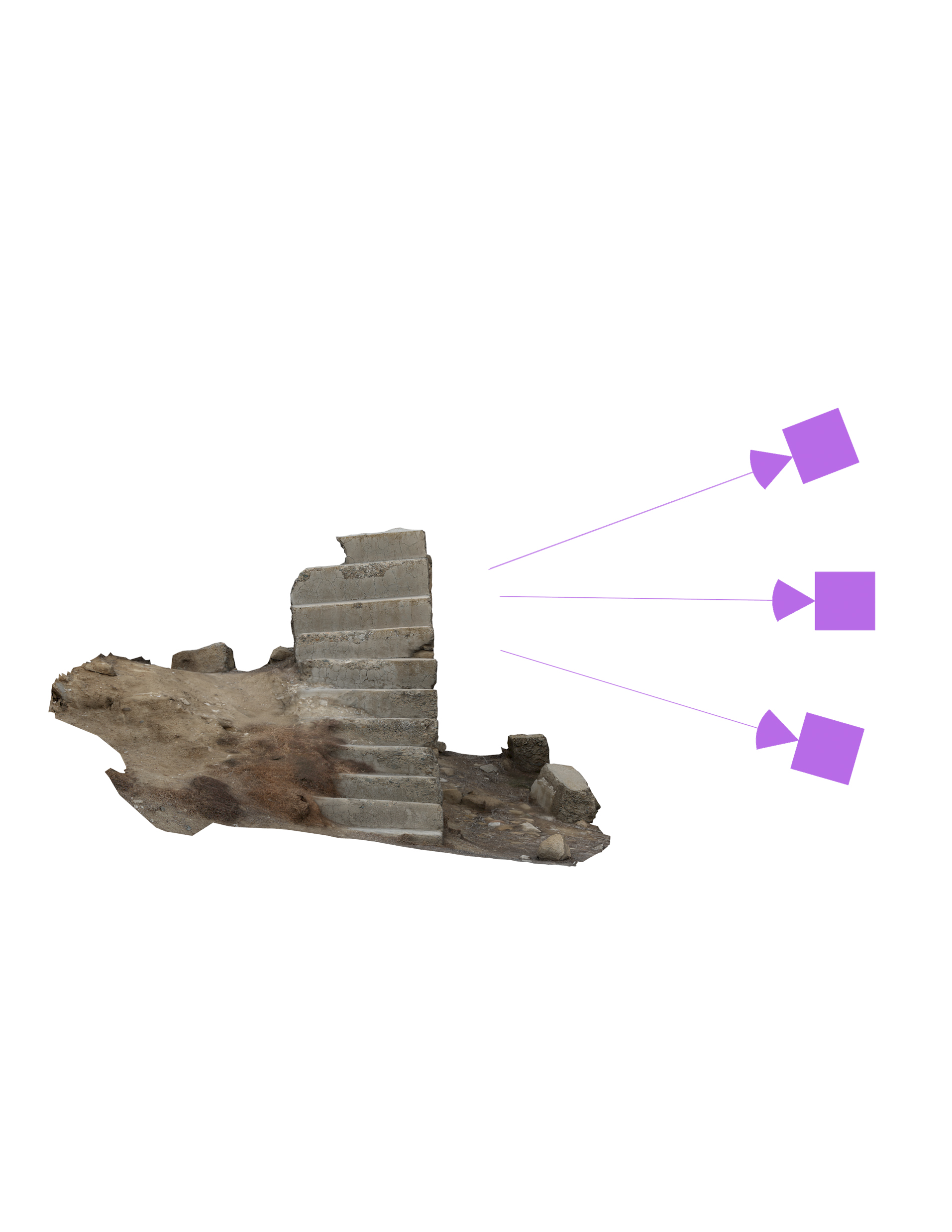
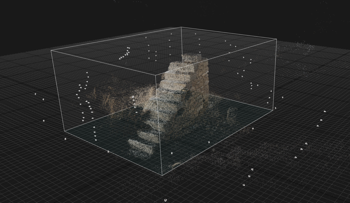
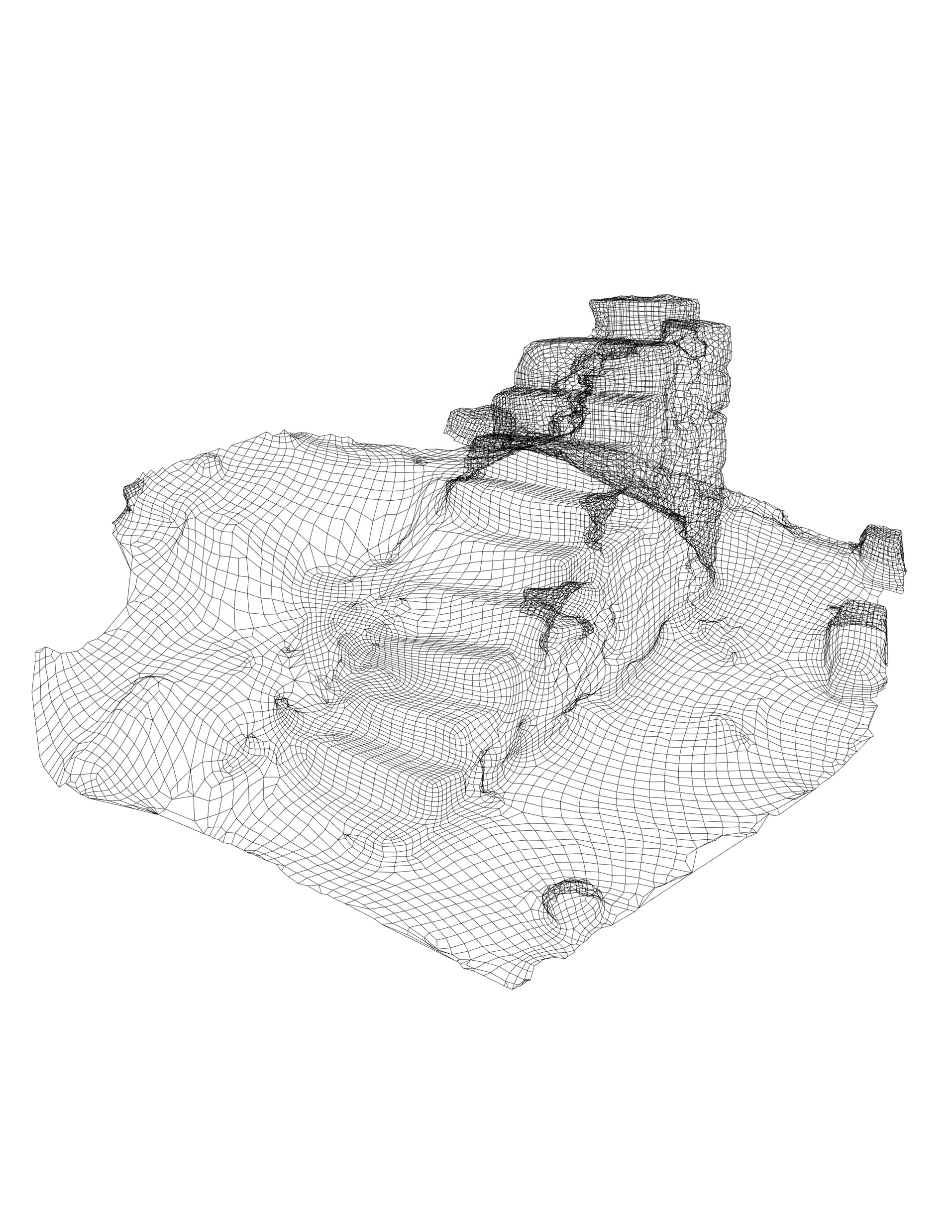
The images were color corrected and processed in Lightroom and then imported into RealityCapture for the generation of the point cloud and initial scans. As this was not going to be game asset and was to be used primarily for analyses, the built-in decimation, UV and texturing tools that RealityCapture features were considered adequate enough for the generation of a workable model.
Analyses
Prior to proceeding with a set of analyses, the model was scaled to its real dimensions using a reference object of known dimensions placed in the scene. It was then imported into Rhino for the creation of the analytical diagrams featured below.
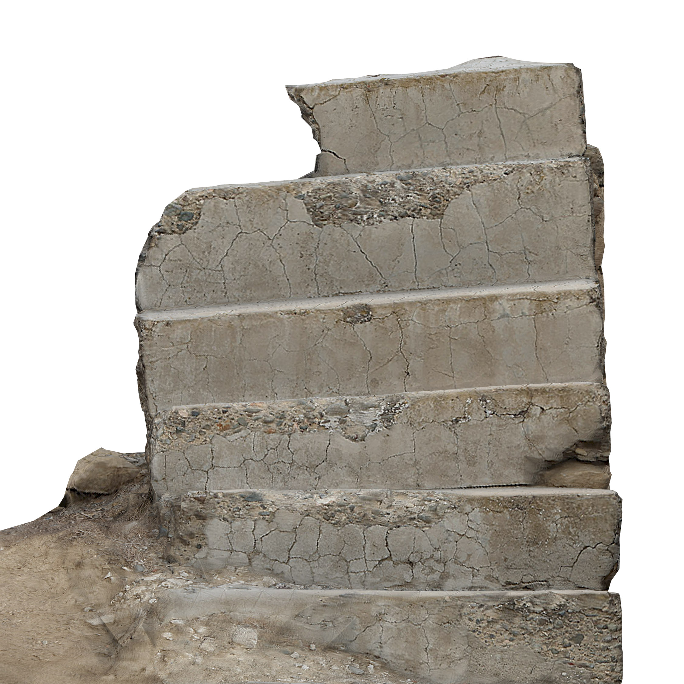
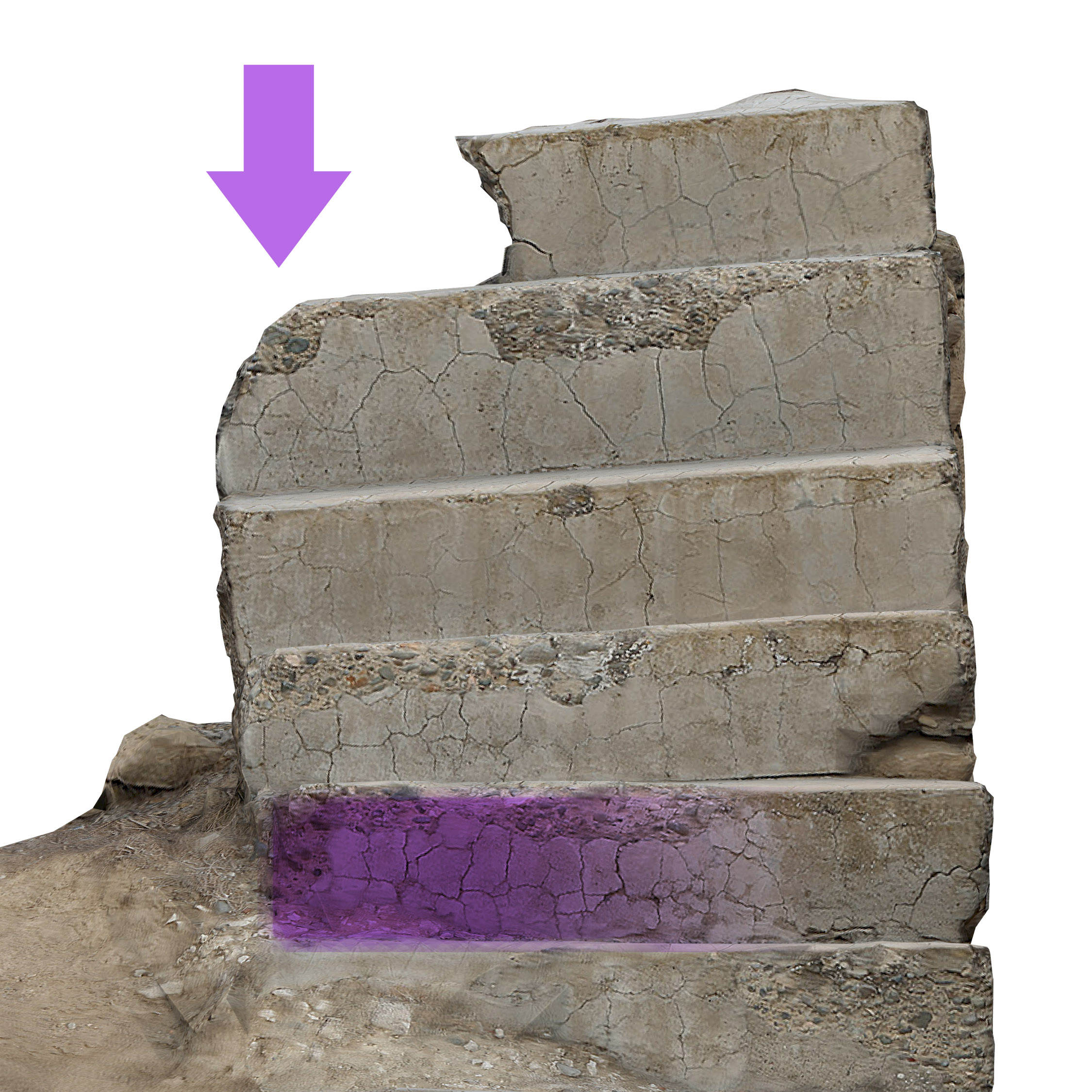
To begin with the deviation from an optimal horizontal line was determined through overlaying a base grid over the scanned model.
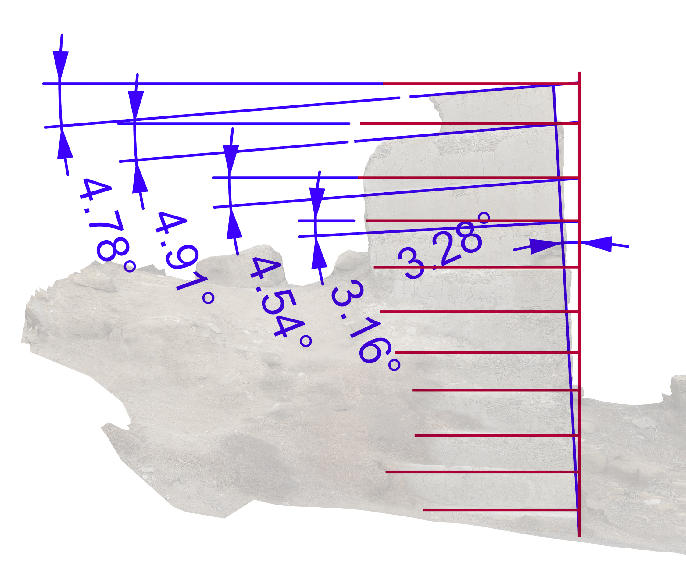
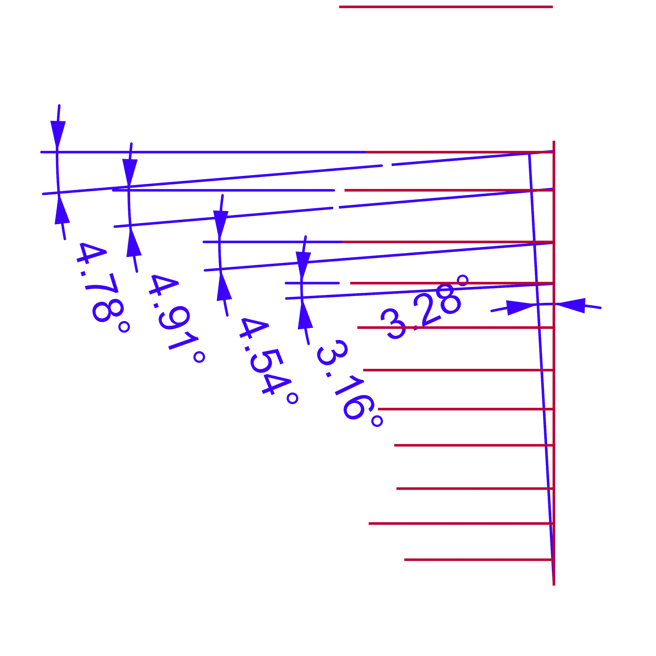
Through this overlay, the angle of deviation, along with the point where said deviation begins was easily determined. By observing the nature of this deviation, it could be hypothesized that this deviation occurred due to an uneven subsidence of the structure around the point of the 6th step. The obvious destruction of the uppermost attachment point of the staircase, further exacerbated this deviation.
This stipulation leads to a closer analysis of individual steps to see if there are additional clues which can further narrow down potentially problematic parts. Due to the textural qualities of the generated model, identifying cracks and other similar deformations is easily carried out.
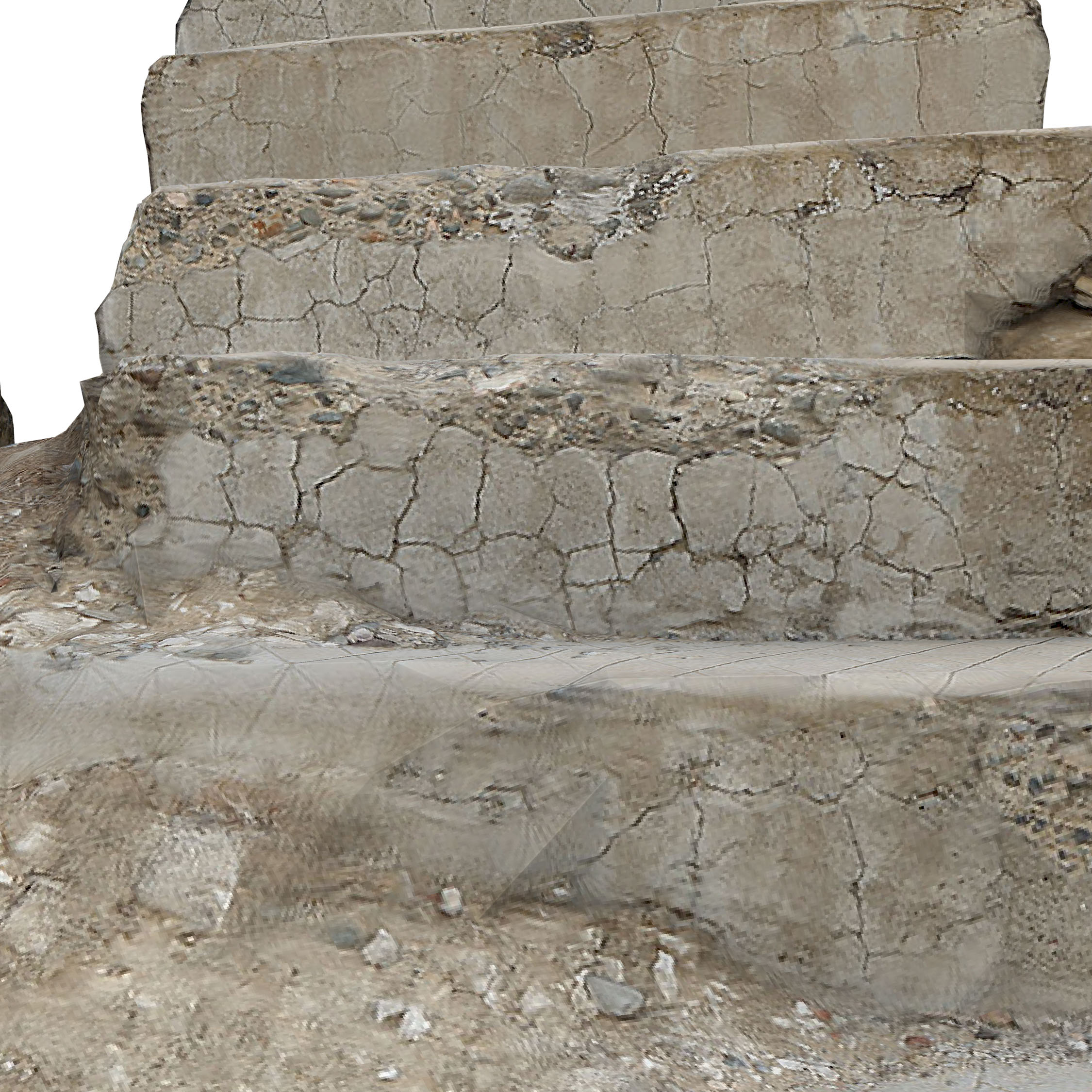
At first glance it can be seen that the most intense cracking is present in the 4th step from the top and primarily on the leftmost part of the staircase. Pictures 3 and 4 in the slideshow above show how the combination of the superior elements’ weight and the lack of adequate lateral support may have led to this damage.
So, in summary, the aggregated weight of the top-most part of the construction has caused excessive compression of the side of the step leading to the cracking of the step.
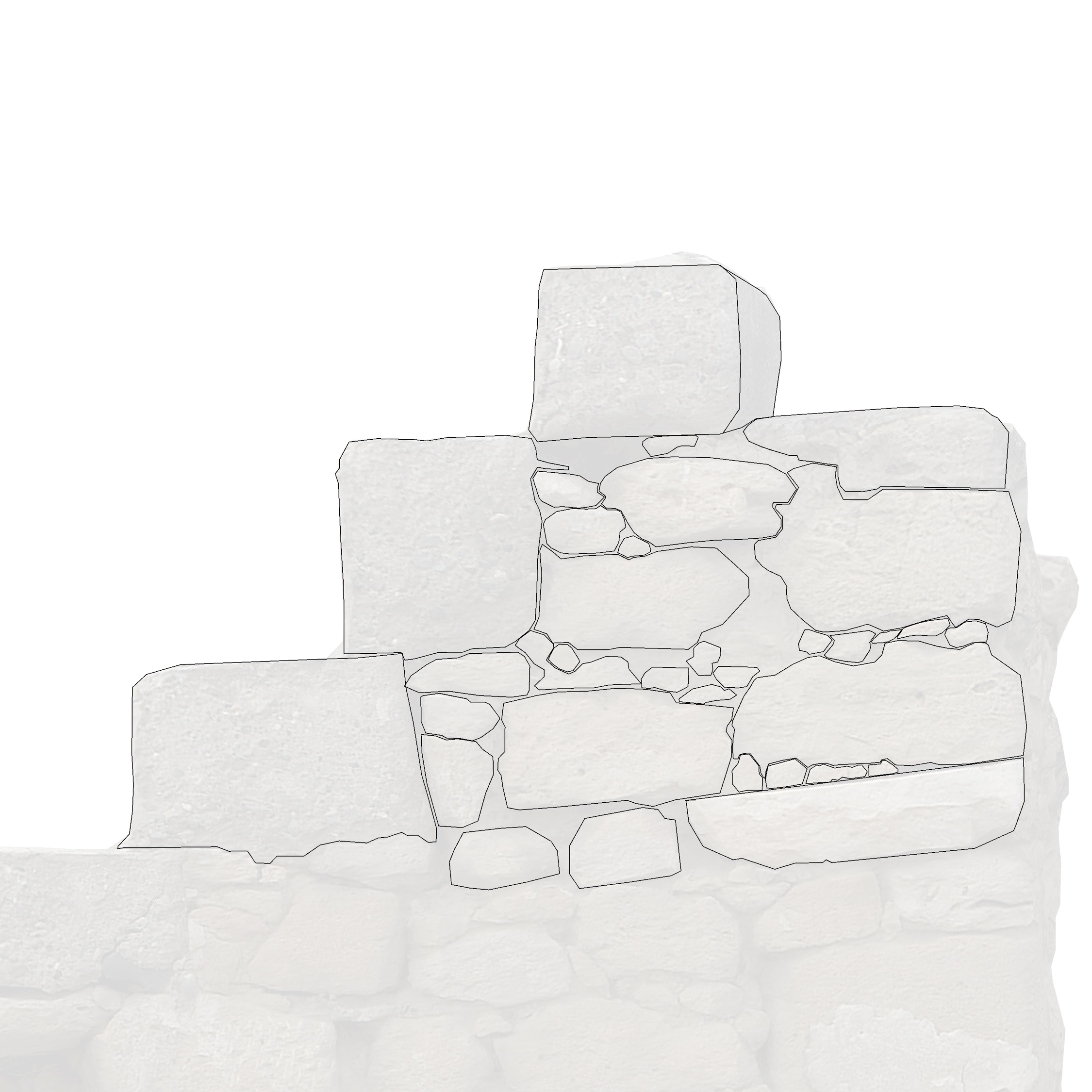
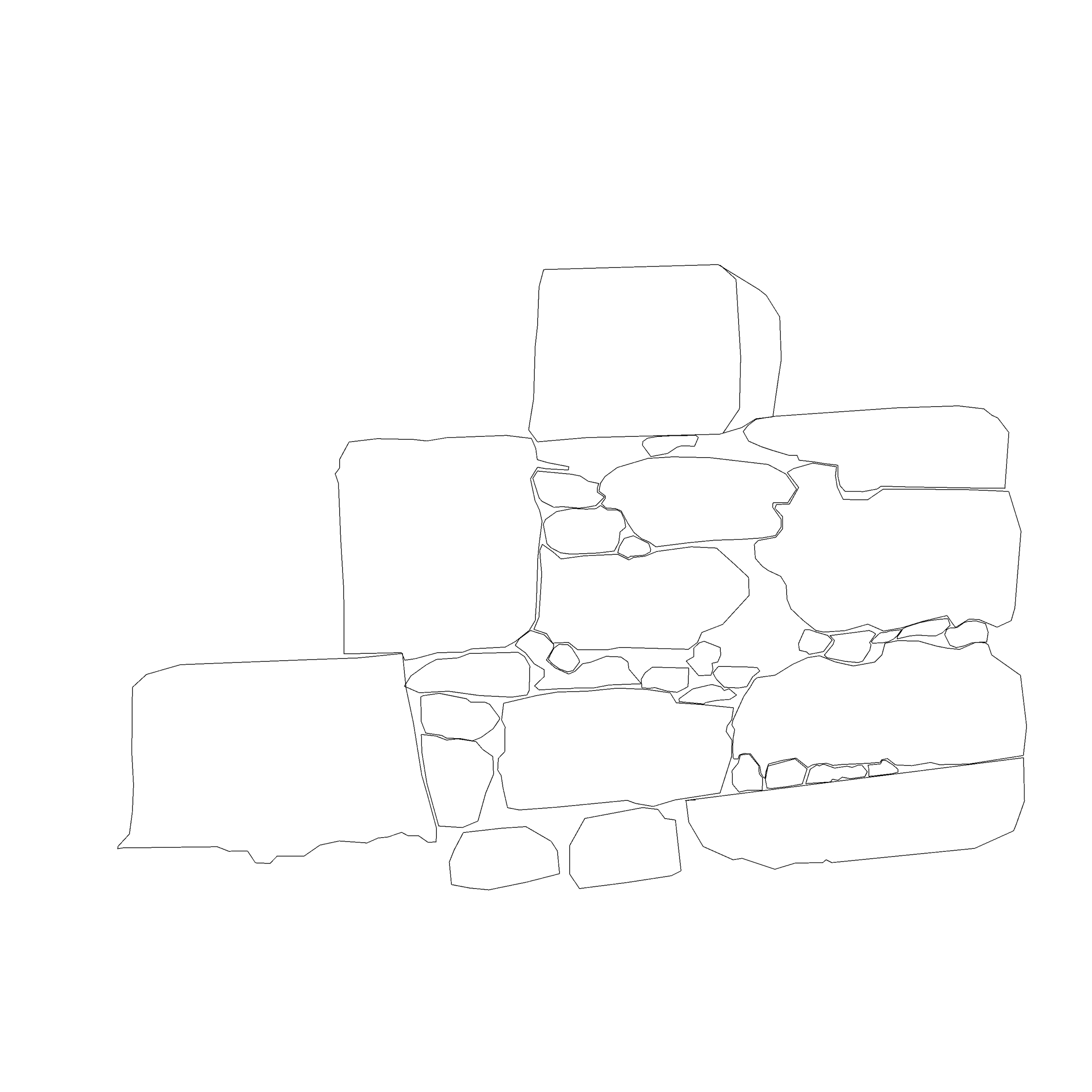
Another benefit of using such scans for analysis is that they can function as orthographic views for the creation of linear drawings and translation to CAD. The following images illustrate an example of a quick way of doing this.
The final analytical exercise carried out on this model was to determine the dimensions of the missing stones from the exposed side of the structure. The scattered debris around the site could include fragments of these stones, but it would be difficult to determine and match the missing parts based on present detritus.
As such, new stone elements have been determined and modeled based on measurements carried out on the cavities and inserted into the existing model.
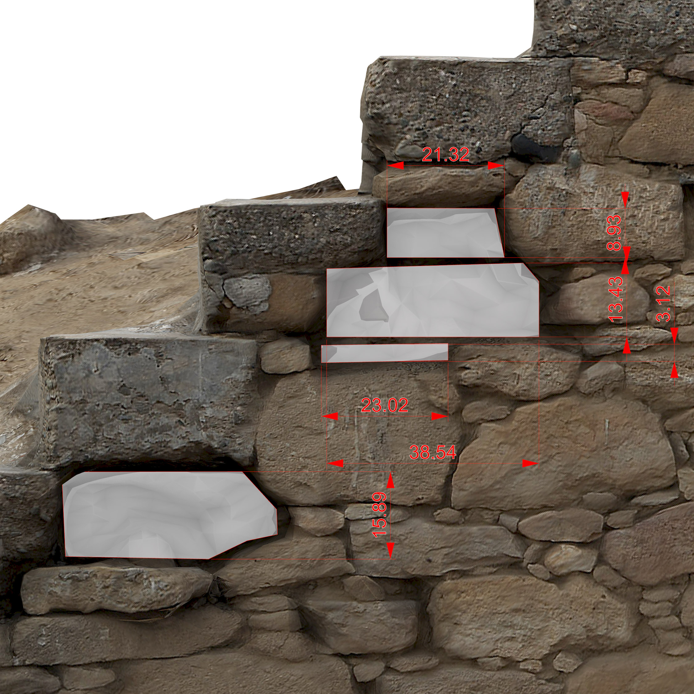
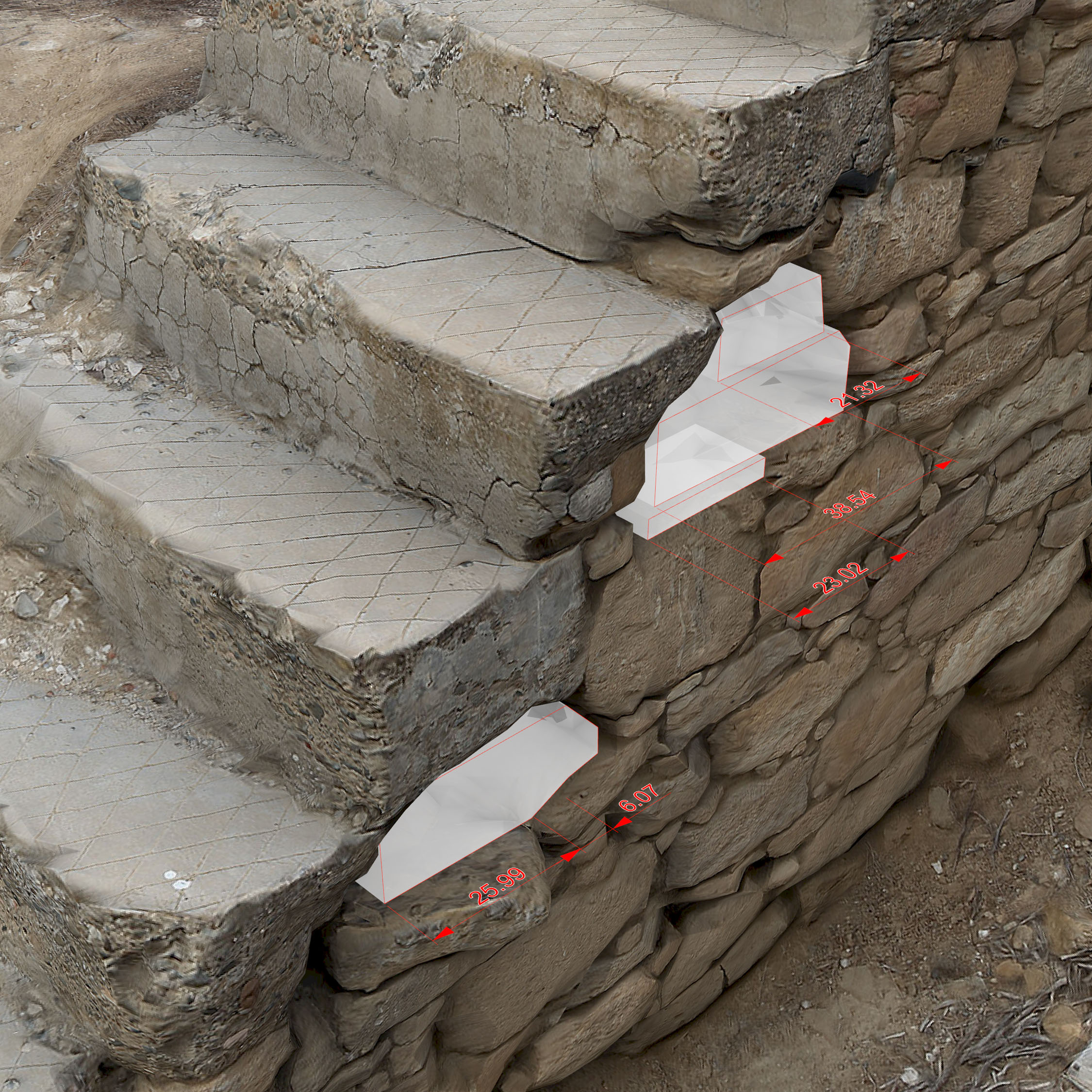
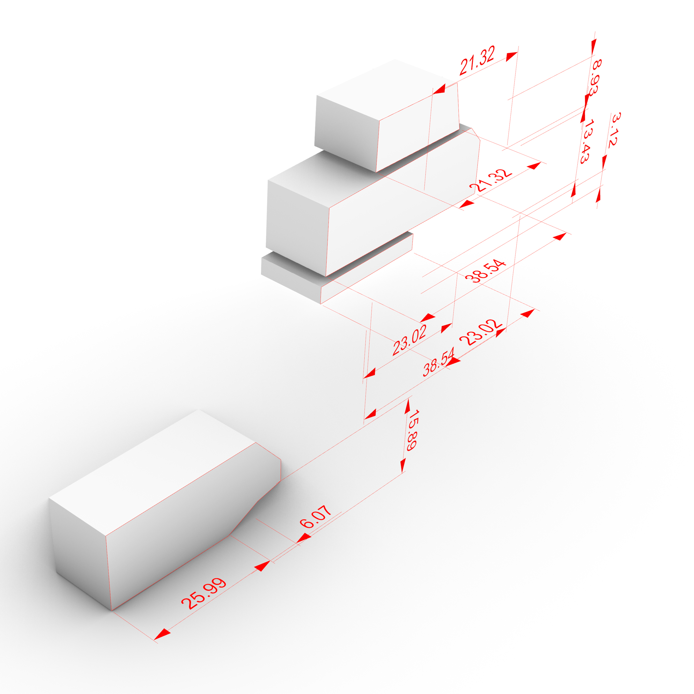
By having the detailed scan model, modeling fitting parts can be accomplished with relevant ease and off-site.
Conclusions
The utilization of scan data of structural elements or of fragments of a larger construction provides a large convenience for subsequent analyses and greatly shortens the time required on-site, as, if scanned properly, the generated model includes a wealth of valuable information which can be analyzed at a later date, without require additional site visits.
All of the analyses carried out on this model were done at a much later date after the site visit. Furthermore, the presence of a dimensionally accurate and feature-rich digital model, facilitates the distribution and collaboration of other, specialized, team members which can contribute to potential analytical and rehabilitative works for a particular project.